The E-MU MP7 Command Station I picked up locally recently had a display that was starting to fade a little on the left hand side.
After searching for a replacement to buy online I came up empty handed. I bought a used replacement from Japan and it was worse than mine, so I looked into making my own.
I won’t go into the boring details but over a month or so I ended up with a couple prototypes after trial and error of ordering different components etc and testing.
If you are in a similar situation of having an E-MU command station or a Proteus 2500 with an LCD display that needs replacing, this article has a list of all the parts you will need to make a replacement with a new color backlight LCD (ghetto OLED).
The total cost for the parts is about $15. It’s a fairly simple soldering job and you can make it in about 15 min, then just swap it out.
I got all the parts from AliExpress but I’m sure everything would be available on Amazon drop shipped from the same suppliers anyway.
Part links are NOT affiliate links or anything of that nature, just what I used and know will work.
Table of Contents
Background on the E-MU Command Station LCD
The E-MU command station LCD’s use the standard 14 pin Hitachi standard. You will likely not be able to find a new LCD with exactly the same pin-out as all new LCD’s follow the newer standard which has 16 pins.
The reason for this is that the older displays draw a bit more voltage for the LCD and to power this and enable the contrast (viewing angle) the E-MU OG display has separate 5v and GND wires on A/K terminals on the opposite side of the ribbon cable (that does everything else). Not all older LCD’s had back lights also.
The replacement displays also have A/K already soldered on the same side, plus pins 15 and 16 on the ribbon side are also BLA/BLK.
The first prototype I made, I soldered the power cable on pins 15 and 16. This did work and loaded the command station OS etc, but it caused errors whenever turning off the E-MU and restarting it would light up the display and show an ‘X’ character – my electronics skills amount to changing the odd soldered battery so I didn’t bother probing further on this but maybe data buffers issue?
The next one I made I left pins 15 and 16 unattached and soldered the power lead directly to A/K on the opposite side – the same as the EMU OG display.
This works perfectly and I have been running it for over a week now with no issues. It is this version I will explain how to make.
E-MU Command Station replacement LCD / OLED Parts List
Command Station LCD Display Replacement
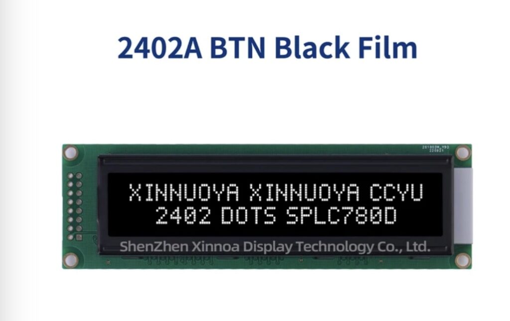
This is the display I used, it’s available in many different colors, some of which actually match the different command station colorways e.g Yellow on black for the XL7, Purple on black for the MP7.
I used white on blue for the initial prototype (too bright), and made final models with both the purple (looks cool on my MP7) and white on black (recommended, best contrast and easy on the eye – what I stuck with).
These are $3.75 each, I would recommend ordering at least 2 in case you mess one up.
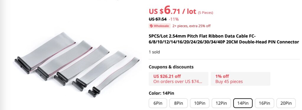
Ribbon Cable
The LCD is attached to the command station main board with a 2.54 pitch 14 pin ribbon data cable.
This is what you want, $6.70 for five:
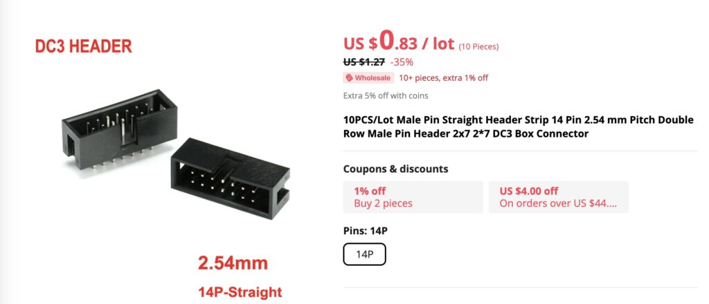
Pin Row Header
This is what is soldered to the LCD and provides the pin plug connection for the ribbon cable.
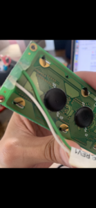
The part I used is a slot header that fits snugly to the ribbon cable – the issue with this is that the E-MU OG display has direct pins/solder to the ribbon cable – this means that the new LCD will not fit into the cutout on the metal LCD plate holder.
I just sawed off one short side edge of the plastic housing before soldering it. Alternatively you can find a naked pin header in the same config, I could not be bothered to wait for another delivery – the sawing job takes 30 seconds. These also come in packs of 10 for $0.83 so you will have plenty of spares.
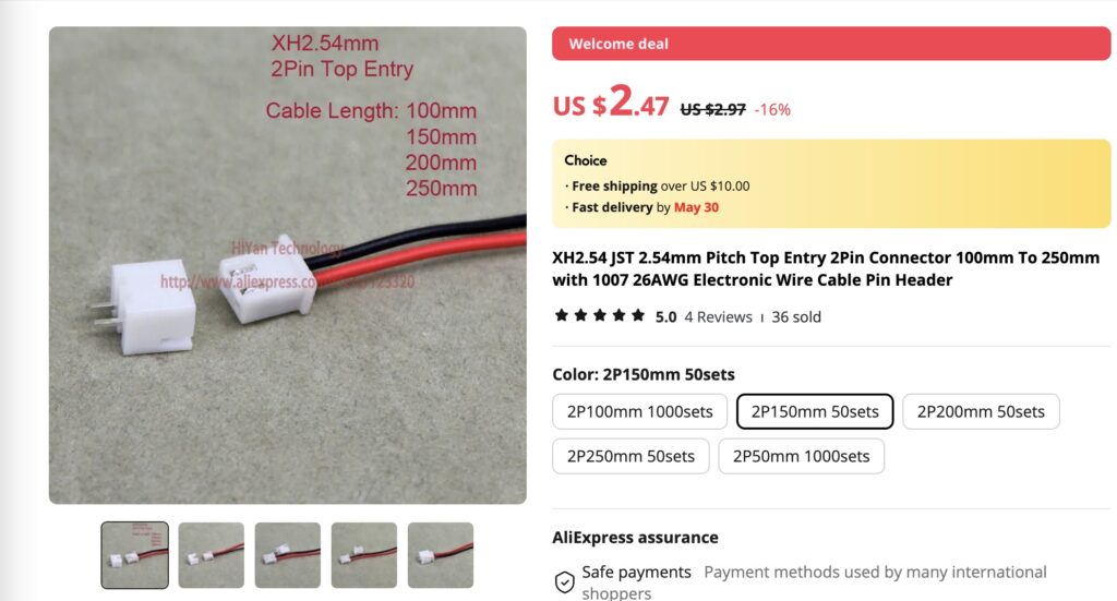
Power (A/K) Lead with 2 pin Connector
This is what gets soldered to the A/K terminals on the display, it’s the lead with green and white wires in your command station.
This is what I used (the white terminal connector on the OG is some kind of custom part I think but the standard 2 pin works fine and plugs in/out with no issues.)
These come with matching terminal connectors that you will not need, you may be able to find just the leads with the plug.
Note for the cautious: These wires are 26AWG, the original E-MU wires are 24AWG. If you can find (or want to make yourself) a connector with 24AWG DO buy that instead, but I have had no issues running with 26AWG (the new LCD’s also consume less power than the OG).
$2.47 for 50.
Soldering Gun and Solder/Paste
Make sure to have solder with flux core if you are not a confident solderer.
Hot Glue (Optional but recommended)
If you look at your command station LCD you will see the A/K soldering has been hot glued over the top, I would recommend doing the same with a decent blob.
How to make the LCD replacement for E-MU Command Stations & Proteus 2500
If you have any electronics/soldering background you will probably be good to run with this as is. For those that don’t, you CAN make this, it’s not rocket science and the soldering is pretty basic, if you don’t feel confident:
- Buy a few replacement LCD’s and plan to fuck up 1 or 2, they are literally like $3.50 each.
- Consider buying a little breadboard kit with a 9V power board for $10, you can then at least test the power up of your creation outside the command station and optionally run other tests by following some Youtube tutorials.
- Consider buying a multimeter, you won’t need to probe anything building this LCD but it’s handy to have when your command station power supply and/or soft power button inevitably goes wrong.
I made mine a while back so unfortunately can’t provide any pics. I have a couple spares I plan to make sometime so if anyone is really stuck and needs a detail step by step with pics/video just drop a comment on the article.
Step 1
Open up your command station, take some pics of the ribbon cable and power leads running to the display.
Unscrew the metal holding plate and take some more pics of all sides of your original LCD, mounting and connectors.
The LCD is screwed to the backing plate -unscrew so you can see the back and take more pics, set it to one side someplace safe.
Step 2
Saw off one side of the short edge of the pin header plastic if you don’t have a naked pin connector.
Step 3
Solder the pin header row to the lcd. The small pins should be poking thru the front of the display, this is where you will solder.
The BACK of the display is the longer pins where the ribbon attaches.
You are soldering from pins 1 to 14. Start with a blob of solder on pins 1 and 14 to hold it in place then work your way thru.
Step 4
Solder the power lead to A and K pins on the opposite side of the board, Red Wire to K, black wire to A.
After cooling and cleaning, finish with hot glue if desired.
Step 5
Test, you can plug in directly to the command station referencing your previously taken pics while it’s opened up, and turn it on to check everything is working.
Note that if you had your display contrast (viewing angle) set to extremes like -7 or +7 this might cause the new display to appear blank, to check this press GLOBAL on the command station, scroll a hard right, press the right cursor once, then try adjusting the contrast.
Troubleshooting
If you followed all the steps it should be working flawlessly. Some things that might be easy fixes.
- Ribbon connector in the wrong way on the command station, if you see lights but no characters try reversing the ribbon connector.
- Soldering not fully connected or joins between pins? Have another go, you will get there.

Hello there,
I’ve just purchased everything as you recommended and as I don’t see any “A” or “K” anywhere on the board – I don’t know where to connect the red and black wires and assume that a mistake there will burn the LCD.
On the LCD board there are 2 connectors on the opposite side:
1. Is connected immediately to the screen via a resistor.
2. Is connected to pin 15.
Any idea which is what ?
Hi James sorry for the late reply I was not recieving notifications of new comments. The boards I bought had the AK clearly labelled but you should be able to dtermine which is which just by the placements of the components which main the original display. Hope you got this sorted anyway.